TR Notes and Queries
Q: Can I run my TR on unleaded fuel?
A: Please see the attached Revington TR information sheet.
Applicable to:
All cars
Q: I have a Revington TR rear damper conversion kit part No. RTR3003RJ. What rate springs shall I use?
A: The Revington TR rear damper conversion is intended for use with uprated
springs. It is possible to use the damper kit with standard springs but
the dampers will have to be set on their lowest setting. Unless the
springs are in perfect condition this setting may prove to be to hard
for some drivers. We recommend springs part No. RTR3101, which provide a
20% uprate, and give ground clearance of 145mm, after all if you are
fitting our dampers you are undoubtedly looking for an improvement in
road handling which these springs will provide in conjunction with our
damper kit.
Order the following parts:
2x RTR3101 Springs
2x SPF2327K Polyurethane Spring Insulators. (Two in each kit) and/or
4x SPF2327-5K Polyurethane Spring Insulators + 5mm deep (Two in each kit)
Applicable to: TR4A; TR250; TR5; TR6CP; TR6CC; TR6CR; TR6CF;
Q: What are the advantages of fitting Revington TR suspension packages?
A: Please see the attached Revington TR information sheet.
Applicable to:
TR2; TR3; TR4; TR4A; TR250; TR5; TR6CP; TR6CC; TR6CR; TR6CF; TRI; TRS;
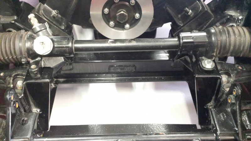
Q: Is any welding required with the RevingtonTR TR2-3B steering rack conversion (RTR3202 series) and if so why and what is involved?
A:
Yes most definitely our rack conversion support brackets are WELDED on. We consider it unsafe to bolt on a kit to the brackets intended to carry the steering box, as the angular moment forces are too great. The chassis brackets crack in this area in standard form without putting more force on them. The welding required is minimal and can be performed with all the suspension and the body in place. One important consideration is that an electric fan will need to be fitted as the original fan and extension will need to be removed as the rack bar, being a larger diameter than the original steering cross shaft, wants to occupy the same space as the fan extension. Lowering the rack is unacceptable as this introduces bump steer which makes the car uncontrollable.
The photographs linked to each part number show the front apron removed and the brackets assembled to the chassis. These are welded onto the chassis which amounts to something like a length of 300mm of welding all in. This should take a competent welder a very short time to complete.
Is the support kit for the upper column bolted on or welded on? Support kits, RTR3406LK and RTR3406RK should not to be confused with the brackets that support the rack. The support bracket is bolted onto the bulkhead and is a kit of standard TR3A parts only needed when a solid full length column is being removed. The kit is required to support the lower end of the upper column where it protrudes through the bulkhead in the engine bay.
How much stripping down is required?
Stripping down is limited to apron off, radiator out, removal of the old steering parts (steering box, idler, cross shaft and track rods), and the engine fan parts that have to be replaced with an electric fan and short bolt set. Also the hubs need to be removed to fit the modified steering arms.
Applicable to:
TR2; TR3; TRI; TRS;
Q: Having changed the clutch components inside the bell housing I now cannot engage 2nd or reverse gears. What could have caused this?
A: The clutch release operation on TR4A - TR6 cars is marginal at best.
Think about when the clutch is worn out, the clutch slips. This is like
disengaging the clutch without even placing your foot on the pedal.
Conversely when the clutch is brand new it follows that the
disengagement point will be at the very end of the pedal travel.
When the components in the pedal box/master cylinder area and the
release parts associated with the slave cylinder are worn, there may in
some cases be insufficient pedal travel to effectively disengage the
clutch thus resulting in clutch drag. Second gear is the gear most
likely to have a worn synchromesh and reverse has none at all making
these gears the most likely candidates for a graunchy gear change under
these circumstances.
The correct solution is to strip everything down and ensure all
components are in perfect condition. This course of action may be
undesirable but even if taken may still result in poor clutch operation
until the clutch is somewhat worn.
The simple solution is to fit an adjustable master cylinder operating
rod. This enables all the slop to be taken out of the system thus
affording maximum pedal travel. Order RTR4136 for TR4A and RTR4357 for
TR5-250-6
Applicable to: TR4A; TR250; TR5; TR6CP; TR6CC; TR6CR; TR6CF;
Q: I'm thinking about changing the original worm and peg steering system on my TR3A to the rack and pinion Steering system fitted to a TR 4 Can I fit a TR4, 5, 250 or TR6 Steering rack to a TR2-3B?
A:
The TR4-6 steering rack is too wide. These cars are wider than the TR2-3B by 100mm This means that the inner ball joints are too far apart and will introduce adverse and unwanted steering effects. The worst of these effects is bump steer. This is where the wheel turns in or out as the wheel rises or falls under suspension loads making the vehicle very unstable especially on undulating surfaces. A well-known racer astounded me once by telling me he had eliminated the effects of bump steer by simply preventing the suspension from moving up or down too far! I could not believe what I was hearing as this is rather like closing the barn door after the horse has bolted! The correct solution if suspension travel is to be maintained is to ensure that the ball joints are in the right place. Not surprisingly Triumph had the suspension geometry correct for the tyres being used in the day. This geometry only requires a small improvement explained later. What you need is our kit part number RTR3202LK (for left hand drive) or RTR3202RK (for RHD). these kits include the correct length rack and employ bracket that weld to the chassis to ensure the correct rigidity and position the rack correctly to ensure the steerign geometry is correct.
If you currently have a solid column, not split, you will also need an upper column Kit 121154X and a support kit RTR3406LK or RTR3406RK. Please remember you will need to alter the horn and indicator arrangement. We have all the necessary switches to do this.
Lastly, the kit improves turn in by altering the Ackerman angle of the steering. To do this we supply redesigned steering arms which move the outer ball joint out sightly to change the Ackerman angle from negative to positive. All prices are available on our website.
Applicable to:
TR2; TR3; TRI; TRS;
Q: How do I measure cylinder head combustion volume?
A: To measure cylinder head combustion chamber volume, grease the valves
and inset these and the spark plugs into the head. Prepare a piece of
clear Perspex large enough to cover the combustion chamber, with two
small holes in it, one. Grease this and slide over the cylinder head to
cover the combustion chamber. Using a syringe or pipette introduce
paraffin, light oil or water via one hole. The other hole lets the air
out. When the chamber is full, read off the syringe or pipette the
amount of fluid introduced in cubic centimetres (millilitres are the
same. This is the volume of the cylinder head.
Applicable to: All cars
Q: How to install SuperPro Polyurethane trailing arm bushes?
A:
Once the old bushes are out ensure the housing for the new
bushes is completely clean. Using the grease supplied the new bushed (without the
sleeve fitted at this stage) can be pressed in using a light press, a vice or can
simply be hammered in with a piece of wood on top of the bush, ensuring of
course that there is a support, the bench for instance, under the specific housing.
When the bush is mostly in, it will 'pop' into place. The sleeve once again
using the grease provided can be pushed in by any of the above means. Alternatively the bush can be pulled in with a threaded steel rod with with double static
nuts, large washer and the bushing at one end and a deep socket, large washer
and nut at the other end. By tightening the nut the fully greased bushing pulls
through the eye hole into the large socket. It should be possible to push the sleeve in by
hand.No other adjustments or reaming is required; the sleeve
is correctly sized to allow the bush to rotate on the sleeve in service.
Applicable to:
All cars
Q: I have a non standard cam in my TR4 and I find the push rods will not fit. I have not shortened the pushrods but have shimmed the rocker shaft pedestals. Is this correct?
A: This not necessarily the right thing to do. You need to establish half
lift of the valves at which point the rocker must be horizontal so that
the rocker operates equally about the centre point. This will require
either shimming the pedestals or milling some off. THEN choose the push
rods to suit. Pushrods longer and shorter are available. See section one
for listings.
Applicable to: TR2; TR3; TR4; TR4A; TR250; TR5; TR6CP; TR6CC; TR6CR; TR6CF; TRI; TRS;
Q: I have excessive negative camber on the front wheels of my TR4A-6. What can cause this?
A: Please see the attached Revington TR information sheet.
Applicable to:
TR4A; TR250; TR5; TR6CP; TR6CC; TR6CR; TR6CF;
Q: I intend fitting a Revington TR overhead throttle kit and notice that you have a single and a double cable version, Which one would be the correct for a road car?
A: The single cable version is fine unless you are racing and need the reassurance
of a constantly available second cable. The cable shouldn't break if the stops at
the pedal as well as the throttle are set correctly.
Applicable to: TR250; TR5; TR6CP; TR6CC; TR6CR; TR6CF;
Q: If I fit a plastic fan to the original fan extension or remove the fan and extension altogether, would I be risking crankshaft breakage or damage due to changing the dampening effect of the original fan/extension arrangement?
A: Irrespective of whether you use a wobbly aluminium fan or a wobbly
plastic fan, the effect is the same. It helps (just) to cool the engine
and that is all. In our opinion the amount of damping it offers is
negligible. Dampers have been in use since the 20's where necessary. If
Triumph (one of the largest sports car manufacturers in the world at the
time) thought is was necessary they would have fitted one. We have been
building TR2-4A engines with no fan and no extension for 25 years with
NO broken crank related failures. As a result we are quite happy that an
engine in good shape, from standard up to all bar the highest revving
competition engines should not suffer ill effect by having the fan
substituted for a later TR6 plastic type or having it and the extension
removed altogether. If you do remove the fan altogether we recommend
using a properly designed washer and bolt arrangement to hold the pulley
to the crankshaft. Order part number RTR1027.
Applicable to: TR2; TR3; TR4; TR4A; TR250; TR5; TR6CP; TR6CC; TR6CR; TR6CF; TRI; TRS;
Q: Is it a good idea to fit a handbrake lever modification to a TR4A-6?
A: Neil Revington explains: Firstly
I am aware of the modification which is little more than a piece of metal
extending the lever at the brake back plate. We have never sold these as to me
as an engineer it misses the point completely.
The TR2-4 hand brake is both a
parking brake and an emergency brake as the cars do not have dual circuits. As
such it can arrest the wheels whist rotating. The TR4A-6 handbrake on the other
hand is a parking brake only. It is only intended to stop the car from moving
whilst at rest. Obvious I know but important; the standard TR4A-6 handbrake is
more than capable of this on any usual gradient.
So where that leaves us is that
if you feel improvement is necessary it is most likely because the system needs
some attention. The obvious areas to look at are seized or partially seized
cables and worn (or missing in the case of slave cylinder gaiters and retention
plates) components but the critical area which is almost universally overlooked
is the brake back plate. When all the plates that hold the slave cylinder in
place are correctly assembled, the cylinder can slide back and forth to allow
the two shoes to take up position in the brake drum. This is essential as the
adjuster at the other end of the shoe is fixed.
With the cylinder removed it can
be seen, on almost all back plates, that a divot has been worn into the
back plate by the handbrake lever pivot bar. This then disallows the cylinder
sliding when the handbrake is applied resulting in only one shoe being pressed
fully onto the drum.
The solution is to remove the
back plate, weld up the divot and linish off the weld to a smooth surface to
restore the correct operation. As is obvious this is beyond a lot of TR owners
who do not have welding equipment and consequently doesn't get done. However it
is not a huge issue to remove the back plates and take them to a local garage
who can affect the repair. With the system reassembled, cables lubricated and
all the plates holding the slave cylinder assembled correctly the handbrake should
operate satisfactorily.
Applicable to:
TR4A; TR250; TR5; TR6CP; TR6CC; TR6CR; TR6CF;
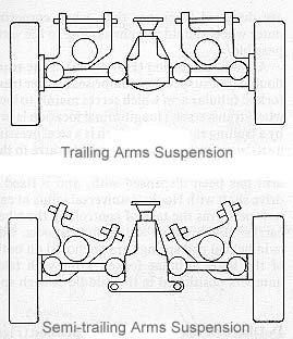
Q: Is the TR4A IRS to TR6 rear suspension arrangement semi trailing arm or trailing arm?
A: The TR4A IRS to TR6 rear suspension is a semi-trailing link suspension
arrangement as the arms are mounted at an angle and not perpendicular to
the wheel base.
Applicable to:
TR4A; TR250; TR5; TR6CP; TR6CC; TR6CR; TR6CF;
Q: What is the initial engine start-up procedure for TR's?
A: Please see the attached Revington TR information sheet.
Applicable to:
All cars
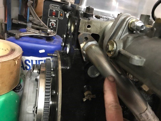
Q: Can I use a 20mm long gearbox long spigot input shaft in a racing (200bhp) application, is the front of the shaft insufficiently supported when fitted to 4 cylinder engine? I race a TR3A in Historic events fitted with a "Police" gearbox.
A:
Further background
The input shaft in this gearbox has 22 teeth on the shaft and 35 on the countershaft gear. The spigot is 20mm long, but I think I need to lengthen this to 33mm, unless a gear exists that has the longer spigot.
I have found the problem with using the 20 mm spigot in a racing (200bhp) application, is that I believe the front of the shaft is not adequately supported when fitted to 4 cylinder engine, and the "skipping rope" action causes jumping out of 4th gear, and eventually, damage to the synchromesh dog teeth.
RevingtonTR Answer
This question is fraught with complications. Trying to use metric dimensions when everything involved is imperial will make matters worse.
I imagine Triumph would have used whatever parts were on the shelf to build a police specification gearbox. Somewhere on the box will be a date stamp saying 22 D 67 or something similar. This would help. Probably on the left hand side of the casing near where the clutch shaft emerges, but could this could be in the same position on the right hand side.
All the TR input shafts have 22 teeth and 35 on the counter gear.
There are 3 different helix angles so whatever is fitted would have to be a matched pair of gears.
Only the early specification used the longer spigot so that would appear the way to go, but....there are 2 bore dimensions to match whatever mainshaft is used and the early one uses a 0.875" spigot so is called imperial. The later one uses a so called metric size, but at 0.833" is neither imperial nor metric. It would be possible to use an imperial mainshaft and early gear pair, but only second hand gears are available. Mainshafts are readily available.
The middle gear pairs are imperial but have a short spigot. You would therefore have to strip the box to ascertain whether the mainshaft is imperial or "metric". Just exposing the spigot will be enough to establish this.
The final suggestion is that whatever input shaft is present, you could extend its length by electron beam welding (although tig might do it) and grinding the nose to size, which seems to be 0.495". This fits in a 0.500" bore sintered bronze bush, so isn't exactly a tight fit anyway. It may be possible to find a needle roller to fit the crank 1" bore, but there won't be anything that mates with a .495" spigot.
You could have a longer spigot bush made, to add maybe 10mm to engage more of the input shaft spigot, in silicon bronze. #
With the Toyota 5 speed conversions we do, we supply a hardened steel thin wall tube (approx. 1mm wall) that is longer than the Toyota input shaft spigot and provided a suitable length is used will extend to the full depth of the spigot bush once tapped fully home onto the input shaft spigot. The spigot bush will in turn need to be bored out approx. 2mm to give 0.005" clearance.
It is important to mention here we have never heard of this all being a problem and it is worth pointing out that we produce race engines at 200 BHP and back in 1988 raced against a well-known competitor with a supercharged car showing 250HP at the wheels. That car managed around 10 full seasons before reliability modification were considered. With that in mind it is important to ensure there is not a mismatch in the gearbox somewhere that is causing a problem.
If you need us to supply you with some parts, once you have established what you need we will be happy to supply. We can also rebuild the gearbox for you.
Applicable to:
TR2; TR3; TR4; TR4A; TR250; TR5; TR6CP; TR6CC; TR6CR; TR6CF; TRI; TRS;
Q: Can I use an Extractor Manifold RTR2044 part of system RTR2042 with a triple Weber inlet manifold RTR4008 and RTR4008-1
A:
Our TR5-6 Extractor Manifold was designed to maximise gas flow specifically with PI inlet manifolds fitted.
These comments are specific to the Weber inlet manifold we supply but may be relevant to other manifolds as well.
Several things have conspired to result in a potential interference problem between the Weber inlet manifold we suply and our exhaust manifold.
1. Our
inlet manifold supplier used to supply TWM then switched to Cannon. TWM used to
fit but we are now aware the Cannon inlet manifold sits lower causing an interference problem with our extractor manifold. We believe the TWM (now not
available as far as we know) manifold was canted up at a steeper angle.
2. Our
Extractor manifold has recently been redesigned to improve access to the mounting
nuts and to optimise gas flow. We did this with the PI manifolds in place but having checked the Cannon inlet manifold there is an interference.
Our extractor manifold gives the best power of anything around, the long
primary outlets are crucial to this power delivery and we don't know of another Weber inlet manifold, so if you are proposing to fit these two parts together then we would suggest the following:-
1.The offending flanges on the inlet manifold can be filed away as much as
possible
2.It is permissible to plannish flats onto the tops of the exhaust tubes ever so
slightly.
It will be surprising how close this brings the exhaust to fitting. However
if this is not enough then the face of the inlet manifold which sits against
the head can be machined to an angle by a couple of degrees to tilt the outboard end of
the manifold up out of the way.
Applicable to:
TR250; TR5; TR6CP; TR6CC; TR6CR; TR6CF;
Q: Does the 4 cylinder TR engine require an harmonic balancer on the front of the engine?
A:
The subject of balancers needs careful consideration. You can be sure that when BMW specify a harmonic balancer for a new engine they don't have an engineer thumbing through a catalogue over a cup of tea looking for one that might just fit- sort of - if modified a bit. It would be more realistic to assume thousands of hours of testing goes into the design for each application.
RevingtonTR have close contacts with a vibration specialist company who have designed a suitable damper for 4 cylinder TR use but agree with us that this only has a primary value above 5000 rpm. We use this damper when we install a billet crank into an engine that will reliably and continually run at 7500rpm. The company in question do work for Bentley so I think it is fair to assume they know what they are talking about. This damper needless to say is intended for use only where the engine fan has been removed.
By contrast Neil Revington's TR2 has no damper on the front of the engine. This engine uses a standard crank and rods and has been used in competition and on the road for over 200,000 miles, much of which will have been at high revs, up to 6500 at times. It suffers no vibration and the engine is as smooth as the day it was built. Neil designed our aluminium pulley over 20 years ago which has been fitted to hundreds of engines built for road and competition use. We have had no complaints of torsional vibration that would need eliminating with a harmonic balancer. Coupled to this we have sold many hundreds of thin fan belt conversion kits incorporating out aluminium crank pulley all over the world with no negative feedback about vibration. Most of these kits are sold with an electric fan indicating their use without the engine fan fitted. It is naive to think the fan fitted to the front of a 4 cylinder TR engine is in some way a damper. The fan is a crude device and its design and the manner in which it is attached to the engine gives no suggestion of it having any anti vibration design intent. It is interesting to consider that the TR250-6 fan is mounted on its crankshaft with an harmonic damper using the exact same part number small rubber bushes that TR's 2-4A use reinforcing the conclusion that they are there to try to prevent vibration being introduced by the fan, not as some form of harmonic balancing of the engines internal components.
Technical speak
A harmonic damper is a device fitted to the front (assuming the drive to the wheels is from the rear) end of the crankshaft of an internal combustion engine. It is essential in engines with long crankshafts (such as straight 6 and straight 8 engines) and is present on most engines as it reduces torsional vibrations that tend to peak at certain speeds. Torsional vibrations can greatly reduce crankshaft life, if not cause instantaneous failure, if the crankshaft runs at or through an internally generated resonance. Because of this, dampers are designed with a specific weight and diameter to reduce mechanical Q factor[1] and therefore damp out crankshaft resonances. Manufacturers will often re-size the damper in the same basic engine when modification to crankshaft material, thickness, weight, or throw is implemented. Even piston size and conrod shape/weight can affect the damper requirement. With this in mind it is clear that dampers are very specific to an individual engine application and cannot with reliability be simply lifted from one application to another without first understanding the characteristics of the donor engine and matching that to the TR engine. It may also be argued that as the TR engine in question is a well-designed 4 cylinder with a massive and stiff crankshaft, that Triumph (who were not stupid and were at the time one of the foremost manufacturers of sports and saloon cars in the world) will have measured all this and concluded a damper was not necessary (Admittedly the bean counters would have had an input into this too!). Bear in mind that Triumph at the same time produced a very successful 6 cylinder engine on which they conclude a damper was necessary.
It is worth noting that early TR conversions to a thin fan belt arrangement used a pulley of another engine, notably an MGB, primarily due to ease of availability and relatively easy adaption to fit the TR2-4A engine. The fact that these dampers are harmonic dampers for their original application is of no relevance in the TR application. Another important consideration is that Triumph for commercial reasons applied limited balancing to their engine construction. Few engines fitted to TR's 2-4A these days will have escaped being rebuilt. This may have been done to a wide range of standards from good to downright appalling. These engines will produce vibration for a number of reasons some of which will be, but not limited to, rotational lack of balance, reciprocating balance and combustion balance. Added to that with twin carburettors an out of balance of the fuel delivery will introduce vibration. None of these vibrations are inherent torsional vibration needing a harmonic balancer. Consequently when an engine has been built correctly and balanced correctly it will be joyously noted that a harmonic balancer is not necessary!
So our conclusion is that the 4 cylinder TR engine does not need a harmonic damper when it is either a standard unit or one constructed with improved but mostly standard components (crank and rods especially) and used within or slightly beyond its designed rev range, especially when the unit had been carefully built and balanced. However, when a different crank, typically a billet crank, is used in conjunction with ʽHʼ or ʽIʼ beam con rods in an engine revving to 7500 rpm then an harmonic balance will be beneficial to some extent but this will be a little bit 'hit or miss' for the reasons stated above vis a vis the amplitude and specific rev range of the harmonics (if any).
[1] In physics and engineering the Quality factor or Q factor is a dimensionless parameter that describes how under-damped an oscillator or resonator is and characterizes a resonator's bandwidth relative to its centre frequency. Higher Q indicates a lower rate of energy loss relative to the stored energy of the resonator; the oscillations die out more slowly.
Kind Regards
Applicable to:
TR2; TR3; TR4; TR4A; TRI; TRS;
Q: How do I know if I have wide or narrow port cylinder head
A:
Only cars exported to the US had narrow port heads, these being fitted to TR250 and early TR6 both with the commission number prefix CC. It is the inlet ports that are different in this respect, the exhaust ports are the same throughout.
All TR5 and all TR6 other than CC prefixed cars have a wide spacing of the inlet ports. If you are considering changing your cylinder head, adding an extractor manifold or fitting a carburettor manifold, including Weber manifold it is essential to know which head you have.
To find out, measure between the inlet ports which are in 3 pairs.
CC cars: 17mm. The gasket usually has slightly larger diameter holes therefore the gap in the gasket will measure 15mm
CP, CF and CR cars: 25mm. The gasket usually has slightly larger diameter holes therefor the gap in the gasket will measure 23mm
Note: - Many TR's have engines and heads from saloon cars fitted so measuring is the only sure way.
Applicable to:
TR250; TR5; TR6CP; TR6CC; TR6CR; TR6CF;
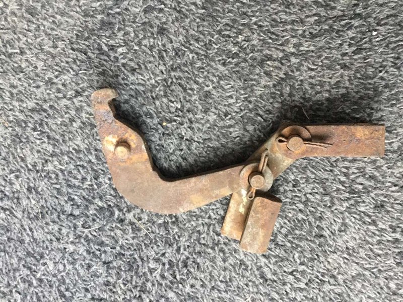
Q: I could do with some assistance in operating the handbrake on steep slopes. Is it advantageous to fit a piece of kit to increase the length of the operating lever at the back plate?
A:
Neil Revington explains: Firstly I am aware of the modification which is
little more than a piece of metal extending the lever at the brake back plate.
We have never sold these as to me as an engineer it misses the point
completely.
The TR2-4 hand brake is both a parking brake and an emergency brake as
the cars do not have dual circuits. As such it can arrest the wheels whilst
rotating. The TR4A-6 handbrake on the other hand is a parking brake only.
Admittedly the TR4A does not have dual circuit brakes as standard, but the industry
was moving that way. This later parking brake is only intended to prevent the
car from moving whilst at rest. Obvious I know but important; the standard
TR4A-6 handbrake is more than capable of this on any usual gradient.
So where that leaves us is that if you feel improvement is necessary it
is most likely because the system needs some attention. The obvious areas to
look at are seized or partially seized cables and worn (or missing in the case
of slave cylinder gaiters and retention plates) components but the critical
area which is almost universally overlooked is the brake back plate. When all
the plates that hold the slave cylinder in place are correctly assembled, the
cylinder can slide back and forth to allow the two shoes to take up position in
the brake drum. This is essential as the adjuster at the other end of the shoe
is fixed.
With the cylinder removed it can be seen, on almost all back plates,
that a divot has been worn into the back plate by the handbrake lever pivot
bar. This occurred over time and can be deep enough to prevent the cylinder from
sliding when the handbrake is applied resulting in only one shoe being pressed
fully onto the drum. This of course means the handbrake is effectively on 50%
efficient.
The solution is to remove the back plate, weld up the divot and linish
off the weld to a smooth surface to restore the correct operation. As is
obvious this is beyond a lot of TR owners who do not have welding equipment and
consequently doesn't get done. However it is not a huge issue to remove the
back plates and take them to a local garage who can affect the repair. With the
system reassembled, cables lubricated and all the plates holding the slave
cylinder assembled correctly and everything that moves lubricated the handbrake
should operate satisfactorily.
Applicable to:
TR4A; TR250; TR5; TR6CP; TR6CC; TR6CR; TR6CF;
Q: I have a new hood/surrey top/tonneau cover which appears to be too small for the car. What can I do?
A:
Firstly most surrey tops, hoods and tonneau (I'll call these 'covers') are made to patterns that have been created from original covers that invariable have been removed from cars that have not been rebuilt. As many of these covers and patterns have been in use for many years it follows that whilst mistakes in manufacture can occur, it is likely that the problem lies elsewhere.
Firstly it is important to ensure the car is the right shape. If the car has been rebuilt and especially if the floor pans and sills have been replaced it is easier for the body shell to end up longer than standard, than it is for it to be shorter. The chassis on TR4A-6 are notoriously weak and can bend in the middle which will result in the rear of the cockpit moving away from the top of the windscreen. Check your car against similar cars of good provenance to ensure your cockpit dimensions are correct. For reference on a car with a backlight frame to accommodate a surrey top, we know the dimension between the holes in the top of the windscreen frame for the surrey spider frame and the holes in the backlight frame to accommodate the spigots of the rear frame is 760mm.
Covers are made from hooding material which can either be vinyl or mohair. These materials when new are relaxed and must be significantly stretched when being fitted to ensure a taut fit in service. This stretching will require significant force which must be aided by ensuring the cover is not just warm but really quite hot, equivalent to a very hot summer's day in direct sunlight so that the cover becomes a floppy bag. In this way the cover will be taut at speed and on seriously hot days and not revert to a floppy bag. This level can be achieved with a hot air gun, hair dryers or a fan heater, ensuring all safety requirements are met. It will be surprising how far the material will stretch and how this amount of stretching when the cover is fitted will result in neat installation with no creases in the material.
Applicable to:
All cars
Q: I have a RevingtonTR rear Disc conversion RTR4410-1K on my TR3A and the bodywork hits the brake hose on full bump. I know this shouldn't happen, what can be causing it?
A:
It is important when making this modification to a TR2-3B that full clearance for the kit is afforded especially where the bodywork flange is concerned. The fitting instructions supplied with the kit show what is required however if an interference occurs, here are some ideas of what might have gone wrong when installing the kit.
1.The callipers are displaced around the axle by one pitch of the 6 bolts
2.The body has not been cut away enough
3.The hose is orientated incorrectly. See the photo called ' front view
with leaf spring in place' in the link below. Change the orientation of the hose to ensure its orientation keeps the hose
out of the way of the body, check carefully on your own installation as this is a crucial safety consideration.
This link takes you to the product page for kit RTR4410-1K where 5 images are available to look at to assist ensuring all parts are assembled as they should be..
4.You have no bump stops fitted to the axle or he bump stop hoops are missing
or the bump stops are misplaced allowing the axle to move too far. follow this link to see the correct standard parts 21,22 and 23
Applicable to:
TR2; TR3; TRI; TRS;
Q: I have fitted a GRB211HD heavy duty clutch release bearing and it makes a shrieking noise when the pedal is first depressed. Is this normal?
A:
New
GRB211HD release bearings have very heavy grease in them when supplied. This means that when the clutch pedal is depressed and the bearing first touches the diaphragm of the clutch cover, it doesn't immediately rotate. This causes a momentary singing or screeching noise which disappears when the pedal is depressed further and the bearing rotates at the same speed as the clutch cover. This situation will continue for a short while until the bearing and its grease loosen up, a few days or weeks perhaps, depending on the amount of gear changes that take place in this time. After this the noise should go away and the clutch should operate normally.
The noise you will hear is the
bearing sliding over the clutch cover diaphragm momentarily as the grease in the release bearing is
initially stiff preventing the bearing from instantly getting up to speed with the
clutch cover diaphragm which can be minimised by firmly depressing the
clutch and not letting the clutch bearing rest on the diaphragm with a light
foot pressure.
It is a good idea not to have the bearing in contact with the diaphragm at all time (this was the practice with TR's 2-4) and this can be achieved by installing a simple spring return device modelled on the TR2-4 system. We have devised a suitable kit to achieve this, order part number
RTR1111K
Applicable to:
TR2; TR3; TR4; TR4A; TR250; TR5; TR6CP; TR6CC; TR6CR; TR6CF; TRI; TRS;
Q: I've got a Revington TR airbox fitted to my car. The lid is not airtight and rattles badly under hard acceleration and the 6 self tapping screws work loose.
How can prevent the rattling and what form of seal/gasket and fasteners work best?
A:
The retention of the lid can be improved by using 'U' nuts on the flange for the self-tapping screws to tighten into. Use
RTR5032 nut and
SS1060462 screw.
Sealant may not really worth it as the small amount of unfiltered
air entering will not affect the engine, however you can make an instant gasket with a tube of RTV rubber sealant. This can be purchased on the internet.
Farnell sell a suitable product.
To ensure the sealant sticks to one side only, say the main part of the box, put cling film on the mating face of the lid and screw the lid down. Then the sealant has set you should have a suitable gasket that will prevent almost all air entering and should prevent rattling too.
Applicable to:
All cars
Q: TR4-6 second and third gears have excessive end-float on the mainshaft. Second gear bush is too short allowing excessive movement over the mainshaft.
A:
There are two combinations of second gear bush and gear. What can happen over time is that the gearbox can be rebuilt with "early" and "late" specification mixed. It is often thought that the later specification must be stronger and Triumph must have made the changes for that reason, technically this is so, but we have found that the dog teeth on the late specification fail much more quickly than the early type did, although the bush part doesn't.
What often occurs is a late specification bush UKC956 and gear TKC454 are mated with the early thrust washers in the range 129941-2-3-4, when what is needed is thrust washers in the range UKC958-9-60-61
The late specification bush is shorter and the bore of the gear is correspondingly short, but the thrust washers are that much thicker, by around .080", which does make the 2nd gear thrust washers less likely to break.
We recommend fitting the early specification gear 105629 plus uprated steel bush 129939X (which is 1 x 153237+1 x 153239 sold as a kit). These must be used with thrust washers 129941-2-3-4. Also we have available a specially made thicker version of 153239 (originally approximately 0.123" thick), which we stock as 153239A (0.126" thick) which may be required to achieve the correct end float, measured using a new circlip 055707.
When correctly fitted to the mainshaft, if (say) 153237 is clamped against the 2nd gear thrust washer, using 153239, it should have 0.003" end float, irrespective of the total end float of the whole cluster on the mainshaft, which we suggest should be 0.004"endfloat. The same end float applies to TKC454 on UKC956, against thrust washers UKC958-9-60-61.
An alternative would be to fit TKC454 gear, UKC956 bush, with thrust washer UKC958-61. More often than not UKC959 is needed. If the gearbox has TKC454 fitted, carefully inspect the dog teeth, and if they are chipped and rounded, throw it away.
If you measure the length of the BORE of the gear, 105629 is approximately 1.375" and UKC956 is approximately 1.187", so it will be hard to mix them up. This measurement can be done with a steel rule for the purposes of establishing which gear you have.
All the thrust washer dimensions are shown on our website against individual part numbers.
Applicable to:
TR2; TR3; TR4; TR4A; TR250; TR5; TR6CP; TR6CC; TR6CR; TR6CF; TRI; TRS;
Q: What is RevingtonTR's Personal Information Policy and how do you use my data?
A:
Personal Data Policy and How RevingtonTR Use and Retain Your Personal Data.
On the 25th May 2018 new regulations covering how personal data can be used and stored will come into effect. In line with every other company in the EU we will have to amend the way we correspond with you and store your data. To see what measures we have taken and how your data is handled please click on the link below.
To read our policy document please CLICK HERE
Applicable to:
All cars
Q: What is the correct definition of a Hood, a Hood Cover a Tonneau and a Surrey Top?
A:
We appreciate that our English terminology (French actually in the case of Tonneau) can sometimes be confusing. Here are our definitions of a Hood, a Hood Cover a Tonneau and a Surrey Top.
In our modern world of global trading terms we use for
products can be confusing. The products in question here are particularly
confusing as for example a hood to us in the UK is the cloth bit over your head,
yet in the USA it is the bit over the engine (a bonnet to us). This FAQ should clear matters up.
A HOOD is the cloth part of the complete hood assembly that goes over the Hoodstick assembly from the rear deck to the top of the windscreen. Confusingly Triumph in some parts books refer to the hood as a hood cover. This is also often referred to in common language as a Soft Top.
A HOOD STOWAGE COVER is a tidy cover over the hood and hoodsticks (hoodsticks only in the case of TR2-3A) when folded away and sits around the back of the cockpit attached to the rear deck. A TR4 does not need one as the hoodsticks are folded behind the cockpit rear squabs. Most Triumph parts books refer to the stowage cover as a Hood Stowage Cover Assembly but in everyday language this cover is often simply refereed to as a hood cover.
A TONNEAU cover goes over the whole cockpit from the rear deck to the base of the windscreen and zips up the middle so it can be used whilst driving or as a complete cover whilst parked.
A SURREY TOP is the cloth part only fitted when the hard centre panel is removed from a hart top TR4, 4A, 250, and 5.
Applicable to:
All cars
